
 Tweet
Tweet
Since it came up in another thread i thought i would do a quick how-to for wiring up LEDs to run off a 12volt system.
it is called a 12volt system but i set mine up to run off of 14volts considering that is closer to what the alternator puts out. i am not sure the difference would matter much at all, but i'd rather add an LED to compensate for the minimal lack in intensity rather than reduce the life of my LEDs.
ok...step #1: buy your LEDs (the rest of the how-to depends on what you get ). i usually just jump on ebay and see what i can find that fits my design. for this write up i will use the example of what i had in my truck....they were designed to run on 3.3volts at 25mA (milliamps). this stuff doesn't much matter but for reference they were 5mm LEDs, blue in color, 8000MCD in brightness.
step #2: calculate what resistor you need to drop your 14volt electrical system down to the voltage and current your LEDs are designed for.
*as a side note, it is fun to take spare LEDs and just hook them up to 14volts...they fry, make sizzling noises, turn brown, and smell bad.
anyway...we take ohms law (flipped for our purposes): resistance = voltage / current. we have 14 volts and want to get that down to 3.3volts. so we have a working voltage of 10.7 (14-3.3) and a current of 0.025amps ( that is the 25milliamps converted to amps). 10.7 / .025 = 428ohms.
now 428 ohms is kinda oddball, so just swing for 430ohm or 450ohm or whatever is closest. it was calculated to a 14 volt system so even 420ohm or slightly less would not hurt.
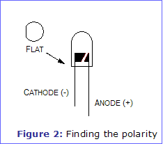
step #3: solder resistors to LEDs. you want to solder the resistor to the positive (+) side of the LED. you can use this pic to determine which is + and which is - as you will need to wire them up correctly after the resistor is soldered on anyway:
this isn't a soldering how-to so i am not going to go into detail but feel free to ask if you want a couple pointers (here's a freebee...heat the wire from below and apply the solder from above).
step #4: wire them up correctly!! this entire how-to was written based on wiring the LEDs in parallel, NOT series. basically, all the LEDs should share a common power source and a common ground but they should NOT be wired one after the other. the power source should branch out to each LED and they should all join back together to go to a common ground. this is the best pic i could find to try and visualize what i am trying to write:

you want the bottom setup, not the top. do not wire them one after the other, wire them each individually but using the same power and ground sources. hopefully this makes sense cause it's important .
.
that being said...make sure your power source is at least 12volts. i find most "12 volt sources" to run anywhere from 12.5 to 13.5 volts with the car on...thus the 14volt consideration at the beginning of the project.
i tried to make this as basic as possible and explain everything the best i can but if you have questions please post them. if i can't help i'm sure someone else on here can!
and this how-to will pretty much work for anything you want to wire into your car that is not designed to run of a 12volt system. the laws of electricity don't change, so just adapt the numbers to fit your situation and you should be all set!
it is called a 12volt system but i set mine up to run off of 14volts considering that is closer to what the alternator puts out. i am not sure the difference would matter much at all, but i'd rather add an LED to compensate for the minimal lack in intensity rather than reduce the life of my LEDs.
ok...step #1: buy your LEDs (the rest of the how-to depends on what you get
step #2: calculate what resistor you need to drop your 14volt electrical system down to the voltage and current your LEDs are designed for.
*as a side note, it is fun to take spare LEDs and just hook them up to 14volts...they fry, make sizzling noises, turn brown, and smell bad.
anyway...we take ohms law (flipped for our purposes): resistance = voltage / current. we have 14 volts and want to get that down to 3.3volts. so we have a working voltage of 10.7 (14-3.3) and a current of 0.025amps ( that is the 25milliamps converted to amps). 10.7 / .025 = 428ohms.
now 428 ohms is kinda oddball, so just swing for 430ohm or 450ohm or whatever is closest. it was calculated to a 14 volt system so even 420ohm or slightly less would not hurt.
step #3: solder resistors to LEDs. you want to solder the resistor to the positive (+) side of the LED. you can use this pic to determine which is + and which is - as you will need to wire them up correctly after the resistor is soldered on anyway:
this isn't a soldering how-to so i am not going to go into detail but feel free to ask if you want a couple pointers (here's a freebee...heat the wire from below and apply the solder from above).
step #4: wire them up correctly!! this entire how-to was written based on wiring the LEDs in parallel, NOT series. basically, all the LEDs should share a common power source and a common ground but they should NOT be wired one after the other. the power source should branch out to each LED and they should all join back together to go to a common ground. this is the best pic i could find to try and visualize what i am trying to write:
you want the bottom setup, not the top. do not wire them one after the other, wire them each individually but using the same power and ground sources. hopefully this makes sense cause it's important
that being said...make sure your power source is at least 12volts. i find most "12 volt sources" to run anywhere from 12.5 to 13.5 volts with the car on...thus the 14volt consideration at the beginning of the project.
i tried to make this as basic as possible and explain everything the best i can but if you have questions please post them. if i can't help i'm sure someone else on here can!
and this how-to will pretty much work for anything you want to wire into your car that is not designed to run of a 12volt system. the laws of electricity don't change, so just adapt the numbers to fit your situation and you should be all set!


Comment